
▶Purpose:
1. Study morphology and diffusion of building blocks in dilute solution.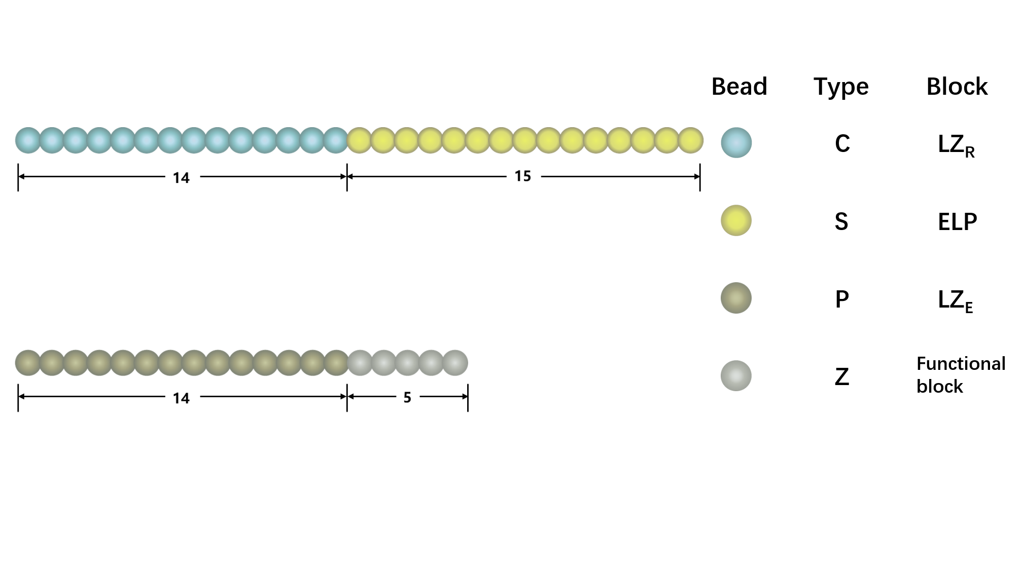
Figure1. The representative architecture of shell polypeptide (A) and core polypeptide (B). There are 29 beads in shell polypeptide and 19 beads in core polypeptide, with blue and yellow beads representing C and S components, gold and silver representing P and A components, respectively,
▶Model and Method:
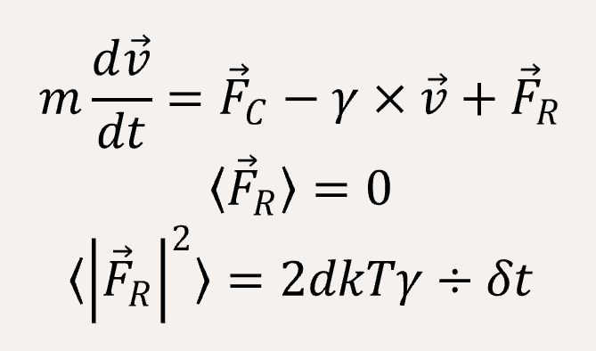
We use a coarse-grained model to represent (EK)10-TAT-LZE and LZR-ELP, as illustrated schematically in Fig.1, according to the estimated ratio of diameter of two building blocks. The length of the ELP part is about 15 while the length of the leucine zipper is about 14 and the length of the functional area is about 5. In Fig.1, each segment of C arms and P arms were given 7 positive charges and 7 negative charges respectively.In Brownian dynamics, the equation of motion of each bead in the system is governed by Langevin equation
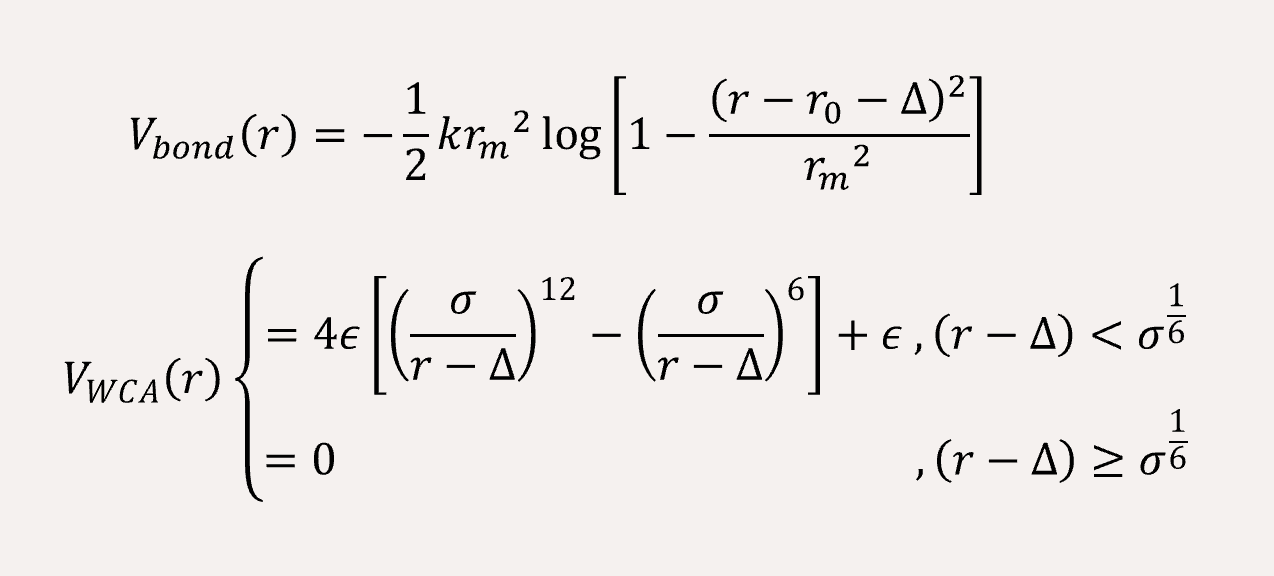
In order to fit a certain rigid amino acid chain, we apply a bond angle potential to the coarse-grained bead chains,

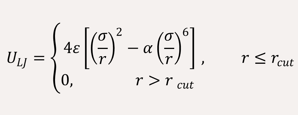
The non-bonded interaction between the coarse-grained beads are represented by Lennard-Jones (LJ) potential,
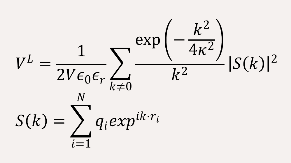
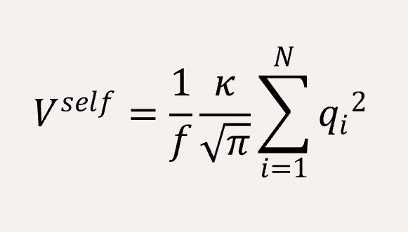
The long-range coulomb interaction between the C type and P type are represented by Ewald summation theory handled in the reciprocal sum.[2]
A time step of δt = 0.005 is used, and the total simulation steps are 5x10⁶. All simulations are performed using with GALAMOST [3] while the results are showing in VMD.[4]
▶Result & Discussion:
At first, we need to ensure our model can exhibit the same conformation with experiment. Since our experiment of assembly may be done by two steps, our self-assembly simulation is also conducted by two separate steps in order to reproduce the actual situation. Totally, simulation have three parts.Study conformation of building blocks in dilute solution.
Before studying the properties of self-assembly, we first simulate the conformation of LZR-ELP and (EK)10-TAT-LZE. The bond angle was set to 180° for C type and P type to give segment of leucine zipper rigidity, meanwhile we set lower k (k=100) value and larger rm(rm=1.5) value for FENE bond potential to increase the flexibility of connection between different types of beads (Fig.2). The segment of leucine zipper has a stronger rigidity thus they can maintain a certain configuration in solution while the segment of ELP is very flexible and exhibits a configuration of random coil in dilute solution. This result shows good anastomosis with CD spectrum and secondary structure prediction of the sequence design, consequently, increasing our simulation credibility.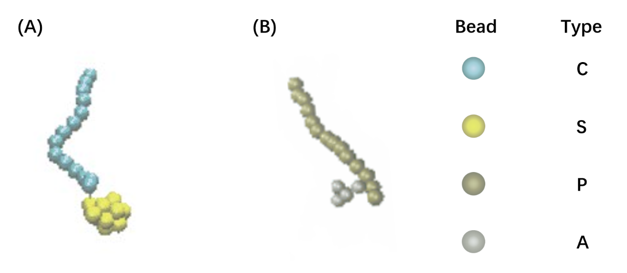
Figure2. The model of LZRM-ELP(A) and (EK)10-TAT-LZE(B).
The (EK)10-TAT-LZE and LZR-ELP were connected by dimerization of leucine zippers, which is mainly achieved by hydrophobic interaction and electrostatic interaction at certain sites. Our leucine zippers have α-helix structure with some charged residues and hydrophobic residues on different directions at one same side of the helix, besides, the leucine zippers of LZR-ELP and (EK)10-TAT-LZE have different charges so assembly specificity can be obtained. But in the coarse-grained simulation, we can see the model only have one kind of bead in one side of the chain, so this kind of specificity of dimerization is hard to be accurately reproduced by our model because we can’t make beads anisotropic to let one bead exhibit different properties at different directions. Therefore, we simplified the interaction of leucine zippers and explored whether dimerization of LZR-ELP and (EK)10-TAT-LZE can be observed in simulation by studying this simplified electrostatic interaction and hydrophilic-hydrophobic interaction from a pair of building blocks.
The C and P segment were given 7 positive charges and 7 negative charges respectively to set up coulomb interaction. The rcut values of Lennard-Jones (LJ) potential for S-C, S-P, S-Z, C-Z, Z-P were set to 1.12 in order to reproduce the effects of hydrophilic-hydrophobic interaction. The simulation result is shown in Fig.3
Figure3. Dimerization between (EK)10-TAT-LZE and LZR-ELP.
Simulate the formation of ERPC.
Figure4. Assembly of LZR-ELP.
Therefore, we set the α value of Lennard-Jones (LJ) potential for S-S to 2.0, while the α value for C-C is set to 0.5. 80 chains are randomly generated in a box of 35x35x35. Result was shown in Fig.4, which reveals that micelle with relatively uniform particle size is formed, and it is consistent with the results of experiment part.
For assembly between L(EK)10-TAT-LZE and LZR-ELP, since the dimerization of leucine zipper is regulated mainly by hydrophobic and electrostatic interaction while hydrogen bonding also plays a supporting role, the interaction between leucine zipper can be strong and complex. To make it feasible to simulate LZR-ELP as the core domain and (EK)10-TAT-LZE as the "shell" with our coarse-grained model, we connect the (EK)10-TAT-LZE and LZR-ELP covalently to simulate the assembly of ERPCs, based on the simulation result of Fig. 3, which indicated that the dimerization of the leucine zipper can be achieved and the fact that hydrogen bond cannot be accurately reproduced in our coarse-grained Brownian dynamic simulation.
C segment and P segment are connected through 6 FENE bonds, 40 building blocks are randomly generated in the box under the same conditions (Fig.5). The result demonstrates that the building block forms a spherical micelle with (EK)10 at the outermost, ELPs in inner part.
Figure5. The assembly of ERPC.
▶Reference:
▶Steered molecular Dynamics Simulation on the interactions between LZR-LZE
▶Model and Method
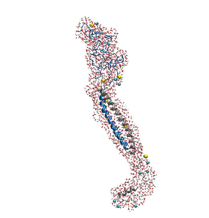
Figure1. An overview of the system. Protein is shown in New Cartoon, with LZR-ELP in blue and (EK)10-TAT-LZE in silver. Water within 4 Å of protein is shown in Licorice with Na+ colored in yellow and Cl- colored in cyan. (B).
Figure2. Equilibrium simulation of (EK)10-TAT-LZE /LZR-ELP.
▶MD protocol
▶Results and Discussion
Figure3. SMD simulations of stretching (EK)10-TAT-LZE away from LZR-ELP.
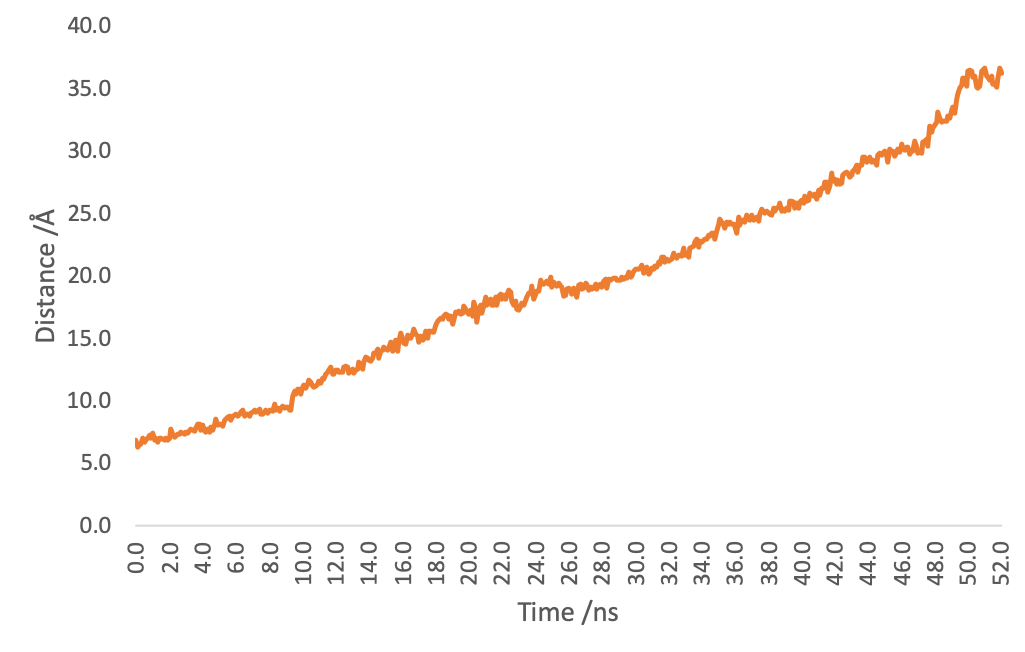
Figure4. Distance of (EK)10-TAT-LZE and LZR-ELP by time.
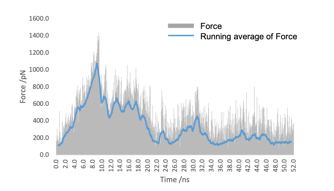
Figure5. The force applied to (EK)10-TAT-LZE to stretch it away from LZR-ELP.
▶Reference: